Physically Based Rendering

an advanced practical

Introduction

What is this?

A small computer graphics project that turned big and into an advanced practical by me, Michael Pronkin, with kind supervision by Prof. Susanne Krömker. Initially I only read about developments in computer graphics turning a new page, reimagining the very long lasting conventional rendering pipeline to achieve more pleasurable visuals and maintaining compatibility for low-ish end devices. Many big names seemed to go in that new direction, I was intrigued so I read a few papers and tried to recreate the idea on my not-very-graphically-capable laptop. To fully understand and experience working with a graphics engine and its pipeline I wrote the whole project with minimal use of third party libraries in pure C++ and OpenGL, creating the GL context using glfw3, using glm for some CPU side GL style math, loading models and materials with assimp and textures/images with stb_image.h. This is my road to implementing the so-called Physically Based Rendering in a custom graphics engine.

So what is Physically Based Rendering?

Modeling the reflection of light in a visually pleasing way has always been a problem in computer graphics. With photorealism being the gold standard for most graphical representations of things, most models have the goal of approaching that look. While the Blinn-Phong model has been used in numerous applications over the past due to its simplicity and low resource consumption, attempts were made to improve the visual appeal at varying costs yet no real replacement for specular reflection in particular had been found that would establish itself as the new standard until the concept of Physically Based Rendering appeared. With many uses in non-realtime rendering like in the CG movie industry, pioneered by Disney, there was also an overhaul of engines in the realtime rendering and game world.

Deeper down the rabbit hole

So roughly the idea of Physically Based Rendering is approaching photorealism by using more physical terms but it is also very commonly associated with a few more practical components that make up the current standard for the rendering pipeline.

A Bidirectional Reflectance Distribution Function, of which there are a few, is one of them. It takes an incoming and outgoing light direction and computes how much light passes through that path. Physically based BRDFs also apply certain rules and restrictions that are present in the real world and are used to approximate that look. This function is then used on every computation involving light and its reflectance to get closer to a physically accurate representation.

Image Based Lighting is what gives the most visual impact on otherwise ordinary scenes in PBR. It is the use of an image as a light source around the 3D objects in a scene. Its actual use is not quite as straightforward though. As roughness of a surface can cause light to scatter, multiple texture fetches and difficult computations would be required to render a single pixel so clever approximations are needed to overcome the costs.

Then a Material system is commonly used to allow for access to the new parameters provided by the physically based BRDFs. There are different types of systems that are basically the same only with some parameters inversed. A simple material system would provide parameters for albedo(a physical way to express the color), roughness, metalness (which is often defined binary but with a factor of mixing of the two metal/nonmetal material properties) and the usual, also previously used in conventional rendering systems, normal, occlusion and sometimes emissive (which describes a material as a lightsource to emit glow).

What are the benefits?

Physically Based Rendering tries to approximate what light does in the physical world as opposed to what we think it does intuitively. This results in a more accurate and natural look. Also light is treated independently of expected color and thus surfaces of all materials have consistently good looks in all environments and lighting conditions.

Bidirectional Reflectance Distribution Functions

Overview

A Bidirectional Reflectance Distribution Function is a function that defines how light is reflected at a point on an opaque surface. It takes an incoming and outgoing light direction and returns the resulting radiance at the reflected light direction. Physically based BRDFs also require positivity (the reflected light to always be positive), Helmholtz reciprocity (the returned value of a BRDF with any two given incoming and outgoing light directions to be equal to the value returned with the light directions swapped) and energy conservation (the total energy in the system to remain constant). Although in practical implementations of physically based BRDFs these rules are sometimes neglected in favor of computational speed when the visual benefits are minimal, at least when it comes to non-scientific graphical needs.

BRDF Lighting Function

$$\Large{f(l, v, n) = Diffuse(l, n) + Specular(l, v, n, h)}$$ $l$ := light direction
$v$ := view direction
$n$ := normal vector
$h$ := light view halfway vector

The currently most widespread BRDF that I also used in this project is the Cook-Torrance Term with the simple Lambert Diffuse Term. The Lambert Term is very common even outside of physically based rendering and only contributes little in terms of physically complex factors while the Cook-Torrance Term consists of three big subterms. The Fresnel Term, Geometric Occlusion Term and Microfacet Distribution Term.

Lambert Diffuse Term

$$\Large{Diffuse(l,n) = l \cdot n}$$ $l$ := light direction
$n$ := normal vector

Cook-Torrance Specular Term

$$\Large{Specular(l, v, n, h) = {F(l, h) G(l, v, h) D(h) \over 4(n \cdot l)(n \cdot v)}}$$ $D$ := Distribution Term
$F$ := Fresnel Term
$G$ := Geometric Occlusion Term
$l$ := light direction
$v$ := view direction
$n$ := normal vector
$h$ := light view halfway vector

Fresnel Term

The Fresnel Term describes the reflection and transmission of light based on the refractive index of a given material and the angle of incidence between the light and the normal. The contribution of the Fresnel Term closes to zero when the light and normal direction are parallel to each other but as the angle becomes increasingly large, the amount of light that reflects becomes greater. At 90° angle of incidence all of the incoming light is reflected, like a mirror, even if the material would otherwise reflect light poorly at normal incidence. Hence this can be a quite unexpected phenomenon for some materials.

Fresnel Term (Schlick-Gauss)

$$\Large{F_{schlick\_gauss}(l, h) = F_0 + (1 - F_0) \times (1 - v \cdot h)^5}$$ $F_0$ := specular reflectance at normal incidence
$l$ := light direction
$h$ := light view halfway vector

Geometric Occlusion Term

Geometric Occlusion accounts for roughness at the microscopic level that causes some light not to be reflected due to very tiny shadows being thrown, some parts to be occluded by other tiny parts and some light to be reflected from bouncing in a a random way from an otherwise invisible direction. So the rougher a material is, the more it behaves diffusely and especially decreases the specular light observed.

Geometric Occlusion Term (Schlick)

$$\Large{G_{schlick}(l, v, h) = G_1(n, l) \times G_1(n, v)}$$ $$\Large{G_1(n, v) = {2 \times (n \cdot v) \over (n \cdot v) + \sqrt{r^2 + (1 - r^2)(n \cdot v)^2}}}$$ $r$ := roughness
$l$ := light direction
$v$ := view direction
$h$ := light view halfway vector

Distribution Term

The last factor, the Distribution Term, predicts the distribution of microfacets. Most common surfaces have microfacets that are distributed evenly around the normal and are called isotropic. Some surfaces, like brushed metal, can have a preference for a certain direction of distribution along the surface and are called anisotropic. Both of these types can be modeled in this term but some implementations only support isotropic surfaces.

Distribution Term (ggx)

$$\Large{D_{ggx}(h) = {r^4 \over \pi ((n \cdot h)^2 \times (r^4 - 1) + 1)^2}}$$ $r$ := roughness
$h$ := light view halfway vector

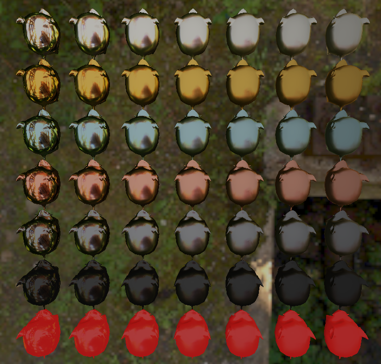
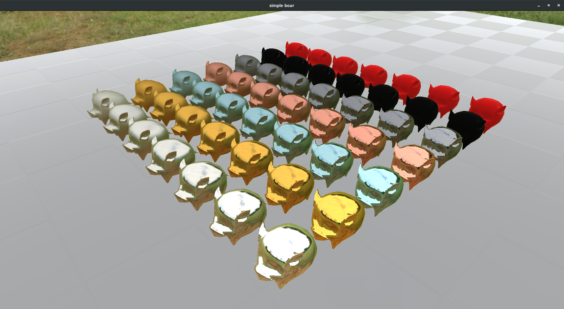
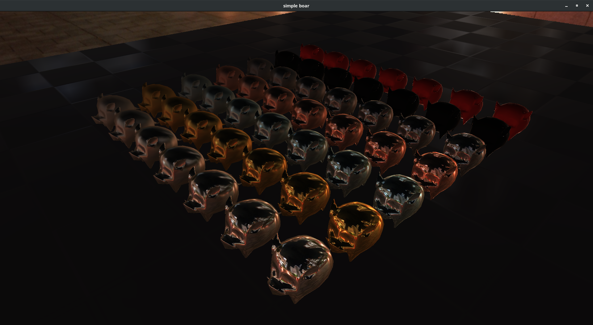
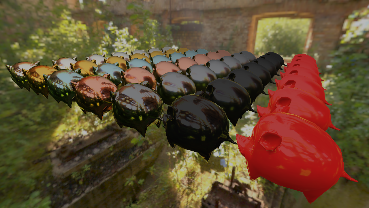
My choice of Functions

For many of these subterms there are different implementations with varying computational overhead, physical accuracy and visual appeal. As a result most researchers and companies tend to handpick their own combination of implementations to suit their current needs. As such this is also what I did, optimizing for performance first, visual appeal second and physical accuracy third. You can see the names of the specific implementations I used in brackets above.

Image Based Lighting

Overview

Image Based Lighting is a rendering technique that, contrary to conventional point or area lights, uses an omnidirectional image as a light source. This way a scene can be lit in very complex ways that would otherwise be very hard to model using more simple lighting techniques due to each pixel in the environment image being treated as a light source with all its color and, for high dynamic range images, intensity.

Practical use

Such environment maps can be made for example by composing real life photos taken in a way that encompasses all directions or rendering a 3D scene and applying a camera transformation that will capture a full 360° view. As such they are fairly easy to make and contribute heavily on the resulting renders of the final scene.

This techinque is prevalent in most Physically Based Rendering engines as, combined with BRDFs, it gives an especially visually effective outcome and most of it's required processing steps can be precomputed to allow for smooth real-time use.

A very smooth metal sphere where the environment map used for ibl can be seen well in its reflection

Materials

Overview

Materials are a way to consistently describe the properties of ab object's surface. They are independent of lighting conditions and look equally well in any environment. Still, they consist of parameters that are intuitive to a designer and are often less complex than their counterparts in conventional renderers due to their decreased interdependence.

The most basic definition of a material's properties consists of albedo, metalness and roughness. Albedo being the description of what color the material reflects and roughness, well, its roughness. Metalness is a little more complicated. Generally materials can be divided into two groups: metals and nonmetals (also called dielectrics). The metal property is often defined to be 0 for dielectrics, where diffuse reflection is taken into account and specular reflection color is white and 1 for metals, where diffuse reflection doesn't exist and specular reflection is tinted by specular color. Any value in between is just a linear interpolation between the two, modeling a semi-translucent layering of the two material types which is the case for things like rust or metallic paint on a car. And with these few properties many materials can be modeled but also scientific scans of material properties in real life can be directly put into this system for more photorealistic purposes.

Here is a bottle rendered in my PBR graphics engine with all the input properties used to render a frame but rendered separately.


click through the different material properties to see them visualized separately.


here you can see the effect of roughness (smooth on the left, rough on the right) on various metal and nonmetal materials


Demo

Here are a few snapshots made in the rendering engine.


A somewhat rough copper Stanford Dragon


My mascot, the boar, a custom model


A boombox showing the use of different materials applied by texture


An old version of the engine where not all physical approximations were done yet.


The same but with a different environment showcasing the adaptability of the material system.


The material testing scene with the final renderer.


Sources

References

Downloads/Resources

About

This is an advanced practical supervised by Prof. Susanne Krömker at Heidelberg University done by


Michael Pronkin

BSc applied computer science