Basics
All objects are stored using a mesh. The shape of the xy-axis is imported from a model. The z-axis is simulated and then interpolated using linear interpolation.
To make it possible to see and interact with objects in time, the meshes of said objects need to be changed. My implementation relies on creating a new triangle mesh in-place using Godots arraymesh. In order to create a new mesh, an array of vertices is needed.
During the simulation...
To make it possible to see and interact with objects in time, the meshes of said objects need to be changed. My implementation relies on creating a new triangle mesh in-place using Godots arraymesh. In order to create a new mesh, an array of vertices is needed.
During the simulation...
Importing mesh
Models are created using modeling software and then imported into Godot. The model itself is then used to extract information about uvs and an outline of our mesh. There are some model requirements that need to be fulfilled:
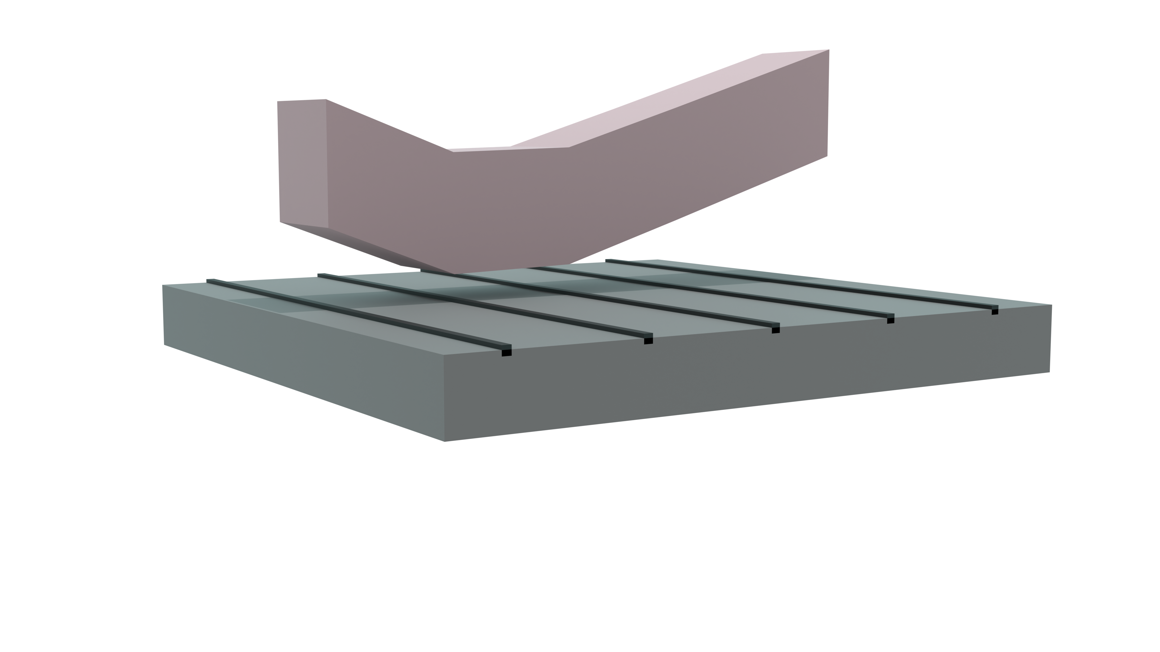
- Outline should be created on xz-axis and then extruded on y-axis (in Blender).
It is important that the different y-vertices share the exact same xy-vertices. In Blender, this is not guaranteed while using its extrude. - The center of the model should be Point (0,0) on xz-axis.
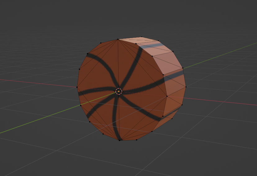
- Shape must be convex.
This is because Godot cannot create collisionshapes using concave meshes and I did not implement it myself.
Creating outline
To create mesh extensions, only the imported objects outline is needed. To create this outline, vertices which share the same xy-coordinate but a different z are removed. With this we have all vertices belonging to the outline, we do however not know how they are connected. That information is usually stored in a separate array containing all faces. To make extensions easier by not having to worry about a second array storing this information, we will change the order of the vertices so neighboring, as well as the last and first array entry, are connected. This can be done because only the edges on the outline are necessary and every vertex on the outline has 2 neighbors. From here on, this property of the array will be called "sorted". To create this array, the code looks at how many faces an edge has. If it is 2 the edge is not part of the outline and can be discarded. If it is 1 it is part of the outline. We now have all vertices and edges belonging to the outline. Now having both the vertices and how they are connected, a new sorted array is created.Importing texture
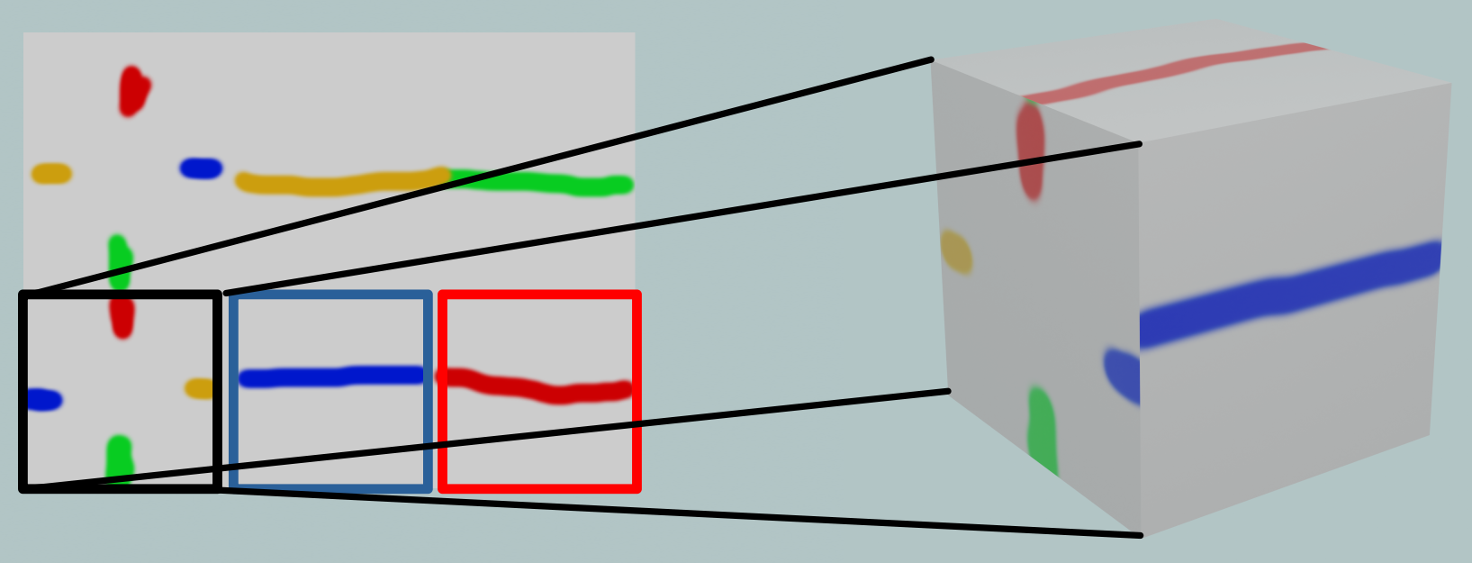
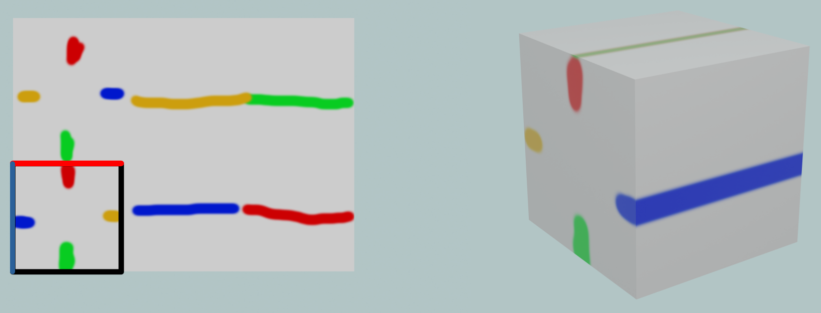
For texture, uv-coordinates are copied over from the imported model. For the texture not oriented towards the z axis, relevant uv-coordinates are copied over as many times as there are extensions to the mesh.These uv-coordinates can be anywhere on the corresponding texture file. For all models, I choose to overlap them with the very edge of the front-facing texture.
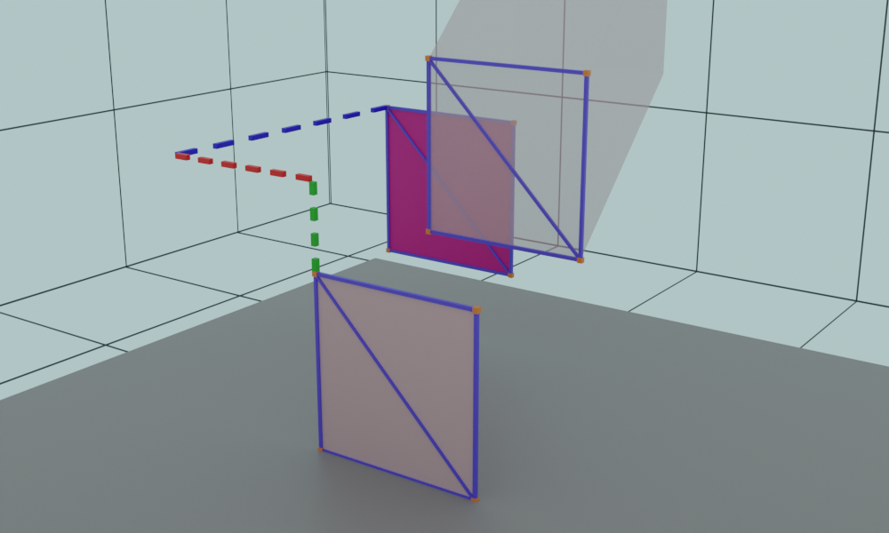
Object/Trajectory selection
Object selection
While no object is selected, if [left mouse button] is pressed, a raycast is performed from the camera pov to determine if there is a suitable object that can be selected. If there is, we move on to Trajectory selection.Trajectory selection
An arrow is created to visualize the trajectory while selecting. To create this we need both the origin of the trajectory, which should be the xy-coordinate center of the selected object, as well as where we want to throw the object to. The latter is calculated by doing a raycast and seeing where it collides with a giant plane collision shape attached to the player character. The former is calculated by first determining the slope between the previous and the next z-vertices of our current z coordinate. Then the previous z-coordinate is subtracted from our current z-coordinate. Using the result with the slope, we can calculate how the objects position changed in relation to the previous z-vertex. Finally, the previous z-vertex is added to get the origin coordinate. When pressing [left mouse button] the trajectory is used as an impulse for the physics simulation.Physics
Currently, a Godot rigidbody with a corresponding in z-axis very thin collisionshape is used for collision detection. The rigidbody is teleported to the starting position and then slid along the z-axis with an impulse determined by the player with trajectory selection. Periodically or on collision with another object, the rigidbodys coordinates are used to extend the mesh towards.Changing the mesh
With an input from trajectory selection, every z-vertex with a higher z-coordinate is deleted. The gap between the previous z-coordinate and the current z-position is filled with an extension. There is an array just for mesh extensions, which excludes for example the faces oriented towards the z-axis. After mesh-extensions are done, all parts of an object mesh are added together. With the mesh complete, a new collisionshape is generated for and assigned to the object.Extending the mesh
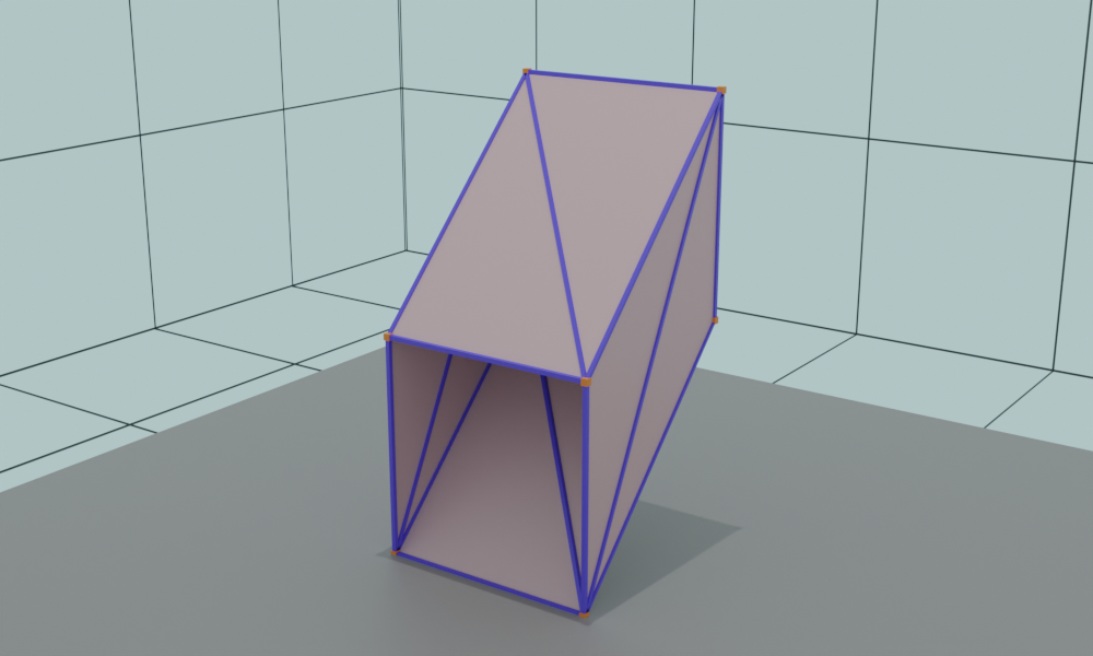
As previously stated, the mesh is created in chunks. For each outline vertex/edge, we need to create two triangle faces for our final mesh. For this, we need the 4 corner positions of the face. These can be determined by:
There is however one issue with this approach. The winding order determines which side of our mesh is visible and which one is see-through (face-culling). The order of our outline vertices is dependent on the original vertex layout created using 3rd party software. Using Blender, the orientation is seemingly random and rather annoying to get right. Therefor, both sides are rendered (by adding each face again, this time the other way around. This happens in the finalization).
- adding together: an outline vertex + the rigidbody coordinate determined in physics
- adding together: the neighboring outline vertex + the rigidbody coordinate determined in physics
- what was position 1 last extension
- what was position 2 last extension
There is however one issue with this approach. The winding order determines which side of our mesh is visible and which one is see-through (face-culling). The order of our outline vertices is dependent on the original vertex layout created using 3rd party software. Using Blender, the orientation is seemingly random and rather annoying to get right. Therefor, both sides are rendered (by adding each face again, this time the other way around. This happens in the finalization).