|
|
|
The Hopf map |
|
Stereographic projection |
|
How all works together |
|
Algorithms |
|
|
|
Algorithms |
|
|
In this section I would like to explain in a little more detail how
the occuring objects are mathematically handled within
HyperView. We will mainly focus on two subjects:
1. Stereographic projection of a circleAs explained in previous sections, the preimage h-1(P) of a point P on S2 is a circle C on S3 whose parametrization is known. The next step in the process of visualization is to project C stereographically into R3. This is why it is crucial to have an efficient algorithm at hand to do this. Of course it would be possible to approximate C by a polygon (i.e. a loop of line segments), project its vertices into R3 and join them again by line segments. The result would be more than ugly, however. Fortunately we can avoid this approximation process and find a geometric solution which provides us with the exact image. In the sequel a description of this solution will be given.First of all, as mentioned earlier, we can interpret stereographic projection of the hypersphere as inversion with respect to another sphere centered at (0,0,0,1) and with radius 1. It is well known that inversion maps circles to circles. Therefore we know the image of our circle C on S3 to be another circle which we will dub C'. What we want is to find out the exact position of C' in R3. To this end we first restrict our attention to a 3-dimensional subspace U of R4 that is spanned by the plane E containing C and the center of inversion Z=(0,0,0,1). This is indeed 3-dimensional if Z does not lie in E (in it does, the situation is even reduced to inversion in the plane, which can be easily dealt with). The following considerations will all take place in U. In U, we can find a unique (3-dimensional) sphere S that contains both C and Z. Its center is the intersection of a line with a certain plane. The line passes through the center of C and is orthogonoal to E. To describe the plane we fix a point Q on C. Then the plane passes through the midpoint of Q and Z and is orthogonal to their join. So far we have described C as the intersection of a plane E with a sphere S passing through the center of inversion Z. Now we apply inversion. From well-known properties of inversion it follows that the image of E is a sphere passing through Z, and the image of S is a plane (crucial for this is the property that Z lies on S). Thus the image C' of the circle C is the intersection of this new sphere with the new plane. Both of these can be easily calculated from the properties of inversion, and this finally provides us with the image of C under inversion/stereographic projection. 2. Modelling Dupin cyclidesWe will not go into too much detail here, but I would like to give an outline of the overall process used in HyperView to draw the cyclides in solid and grid style. The algorithm is mainly based on the article "Shape of toric surfaces" by Rimvydas Krasauskas (see the links section). He gives a parametrization of the cyclide with two projective parameters, which must still be stereographically projected in order to give the final cyclide. Each of the two projective parameters is converted to affine parameters using a covering of the projective line RP1 by two affine charts. This results in four surface patches covering the entire cyclide as illustrated in the following picture.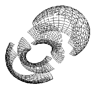 These patches are drawn using the evaluators interface of OpenGL that provides a means of drawing Bézier surfaces. Therefore we first calculate a parametrization of the projected cyclide (using MAPLE). Until now we still work in projective space in order to avoid ugly denominators. Next we express the resulting polynomials in each coordinate in the Bernstein basis (a basis of the space of polynomials up to a given degree) which gives the coefficients we need to plug into the OpenGL interface. Then the OpenGL engine does the rest for us. We still need to say a few words about the role of the parameters a,b,c and d ocurring in Krasauskas' parametrization. Interestingly, they are reflected in a very direct way in the cyclide's appearence, namely in the following way. Imagine a "vertical" plane cutting two circles out of the cyclide as in the following picture. 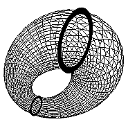 Call the smaller and the larger circle C1 and C2 respectively and denote their radii by r1 and r2 respectively. Then r1 is given by (d-c) and r2 equals (d+c), from which c and d can be deduced as c=(r2-r1)/2 and d=(r2+r1)/2. Futhermore, there is a unique circle C3 (not shown in the picture) whose diameter is the line segment joining the centers of C1 and C2 which lies in the plane orthogonal to the plane containing C1 and C2. The radius of C3 is given by a. Finally, b can be calculated as the positive solution of the equation b2=a2-c2 (which is given in Krasauskas' article). When "GRID" or "SOLID" HyperView are chosen as drawing method for the cyclide, the program first determines the four points of intersection of the circles C1 and C2 with the line joining their centers (the "major axis" of the cyclide). This in turn is done by calculating the two uniquely determined circles H1 and H2 in the CIRCS style (which result as stereographic projections of certain Hopf circles (for the definition of this term see the Hopf map section) containing these four points (the following picture hopefully illustrates this; it shows the circles C1 and C2, the cyclide's major axis as well as H1 and H2 that contain the four above mentioned points of intersection). 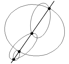 By the way, how are H1 and H2 determined? Let K be the circle on S2 which defines the cyclide. Let further R and S be the points on K whose distance from (-1,0,0) is smallest and largest respectively. Then H1 and H2 are the stereographic projections of h-1(R) and h-1(S). The reason for this is that H1 and H2 are the smallest/largest circle drawn in CIRCS style, thus they are the projections of those Hopf circles lying nearest at/furthest from the center of projection Z=(0,0,0,1). The details are left to the reader. Once the four points of intersection of C1 and C2 with the major axis are found, the radii r1 and r2 from above can be calculated as described. Then the parameters a, b, c and d are determined and the cyclide is drawn. Finally, the four surface patches have to be moved to the correct position and the entire cyclide must be rotated about its major axis. The necessary data is also determined empirically from the "CIRCS" style. As soon as all this is done, the patches are drawn and a texture is applied in order to improve its visual appearence (it may be doubted, though, if this goal has been achieved :-) |
|
|
|
![]()
© 2003 by Maximilian Albert • Anhalter42@gmx.de