|
Kiretu
|
Kiretu contains four classes for creating a point cloud:
This page describes the functionality of the classes. It concentrates on the theoretical background of the classes. For aspects of programming see Data Structures.
The YMLParser imports the Kinect specific calibration file which includes the Kinect’s extrinsics and the depth- and RGB-camera’s intrinsics. Afterwards, it parses all the parameters.
The FrameGrabber captures frames of the depth- RGB-camera. One problem of the depth-stream is image noise (concerning the depth-values). You can see this at the glview depth map:
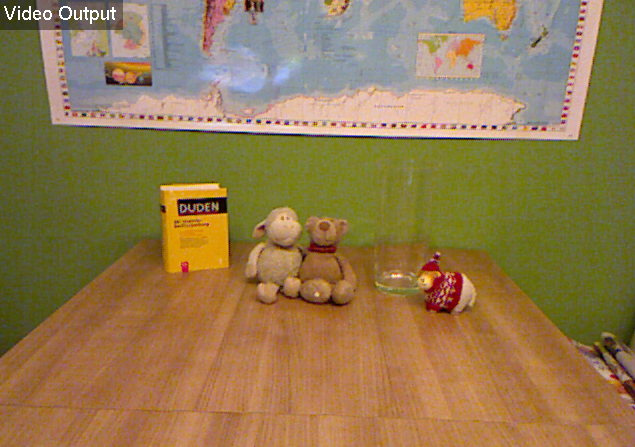
I analyzed this issue capturing the following test scene showing objects with different materials and degrees of reflection:
To get as many valid depth-values as possible, the FrameGrabber is able to grab a variable number of frames (images). A depth-value  is called valid, if
  . After grabbing all frames, it computes the mean of each pixel’s valid depth values.
Here you can see relation between the number of frames and points (concerning the test scene):
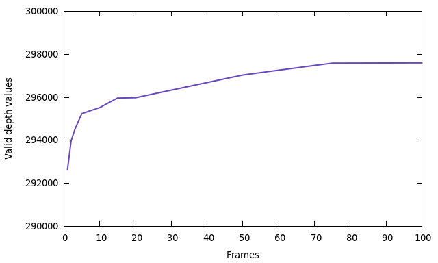
I choose 50 frames as a compromise between the number of points and the time of capturing.
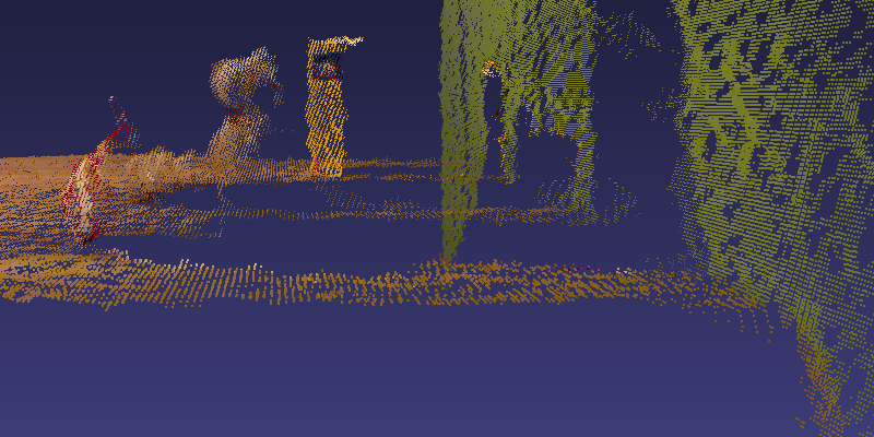
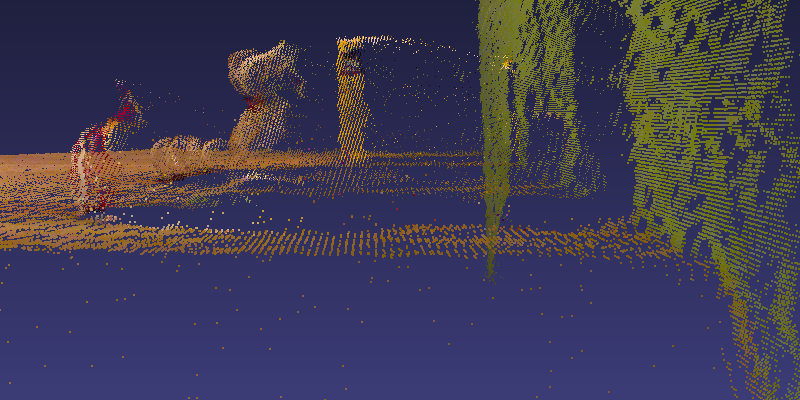
A problem occurs, if the depth values of a pixel vary too much over the frames. E. g. the pixels at an object’s edge, which switch between the object’s depth and background’s depth behind the object. You can see this effect in the following two images. Both show a point cloud of the test scene. At the first picture, only one frame was captured. The second image shows the problematic points after taking the mean of 50 frames.
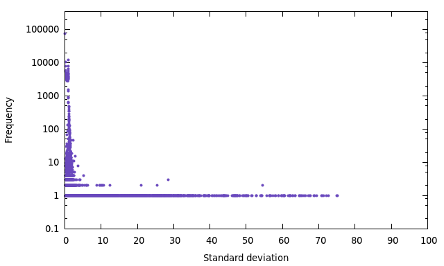
The affected points are characterized by highly varying depth values. As measure of this diversity is the standard deviation [1]. For this reason it is useful to take a look at the frequency of the standard deviation of the depth values around the equivalent mean:
Now, the idea is to use the standard deviation  as a threshold to recognize and sort out problematic points. This implicates, that the value of determines the final number of points. Here you can see the total number of points depending on the standard deviation:
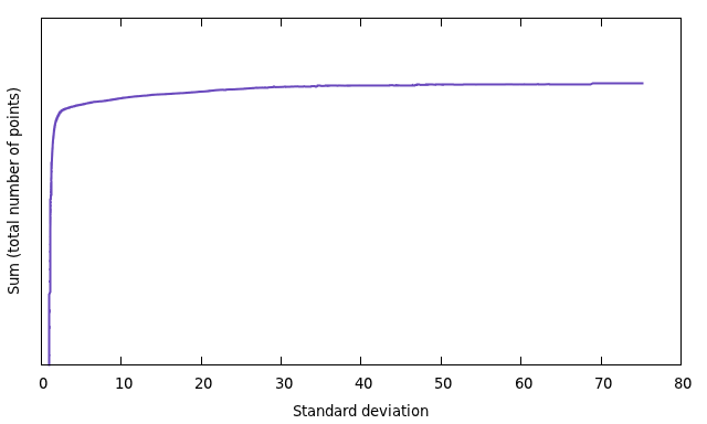
I choose  as the default value.
Finally, the question is, how many valid values can be achieved by this optimization. Here are the results (maximum  ):
):
| 1 frame | 292650 points | |
| 50 frames without threshold | 297038 points | (+4388, 1.5 %) |
| 50 frames with threshold | 295461 points | (+2811, 1.0 %) |
Based on the content of Reconstruction, this section explains how the reconstruction of the point cloud is done by KinectCloud.
Important: All references to equations refer to the numbers given in Reconstruction.
First, you have to convert the raw depth-values of Kinect ( ![$ Z_\mathsf{raw} \in [0, 2047] $](form_62.png) ) into meters. This is done by the following, experimental determined formula [2]:
) into meters. This is done by the following, experimental determined formula [2]:
![\[ Z_\mathsf{meter} = \frac{1}{Z_\mathsf{raw} \cdot (-0.0030711016) + 3.3309495161} \]](form_63.png)
Then, we project the depth-image into the threedimensional space. Let  be a pixel at the captured depth-image and
  the depth value of the pixel, converted into meter. Using equation (5), the
  - and
- and  -coordinate of the equivalent threedimensional point
  can be computed as follows:
![\begin{align*} \begin{pmatrix} x_\mathsf{d} \\ y_\mathsf{d} \\ 1 \end{pmatrix} &= \begin{pmatrix} f_x & 0 & c_x & 0 \\ 0 & f_y & c_y & 0 \\ 0 & 0 & 1 & 0 \end{pmatrix} \begin{pmatrix} X_\mathsf{d} \\ Y_\mathsf{d} \\ Z_\mathsf{d} \\ 1 \end{pmatrix} \\ \Leftrightarrow\ \begin{pmatrix} x_\mathsf{d} \\ y_\mathsf{d} \\ 1 \end{pmatrix} &= \begin{pmatrix} f_xX_\mathsf{d} + c_xZ_\mathsf{d} \\ f_yY_\mathsf{d} + c_yZ_\mathsf{d} \\ Z_\mathsf{d} \end{pmatrix} \stackrel{\mathsf{(4)}}{=} \begin{pmatrix} f_xX_\mathsf{d}/Z_\mathsf{d} + c_x \\ f_yY_\mathsf{d}/Z_\mathsf{d} + c_y \\ 1 \end{pmatrix} \\[0.5cm] X_\mathsf{d} &= \frac{(x_\mathsf{d} - c_x) \cdot Z_\mathsf{d}}{f_x},\quad Y_\mathsf{d} = \frac{(y_\mathsf{d} - c_y) \cdot Z_\mathsf{d}}{f_y} \end{align*}](form_69.png)
Regard, that  and
and  are the parameters of the depth-camera!
The point cloud is given in coordinates of the depth-camera’s coordinate system. We now have to transform all points to the RGB-camera’s coordinate system. This is done by applying the extrinsic parameters to each point:
![\[ \begin{pmatrix} X_\mathsf{rgb} \\ Y_\mathsf{rgb} \\ Z_\mathsf{rgb} \end{pmatrix} = \begin{pmatrix} r_{11} & r_{12} & r_{13} \\ r_{21} & r_{22} & r_{23} \\ r_{31} & r_{32} & r_{33} \end{pmatrix} \begin{pmatrix} X_\mathsf{d} \\ Y_\mathsf{d} \\ Z_\mathsf{d} \end{pmatrix} + \begin{pmatrix} t_1 \\ t_2 \\ t_3 \end{pmatrix} \]](form_72.png)
Finally, we reproject the point cloud onto the RGB-image to get the equivalent color of each point. Therefor, we can use equation (5), again. Let  be the point in the space. We can compute the corresponding pixel
  at the RGB-image as follows:
![\begin{align*} \begin{pmatrix} x_\mathsf{rgb} \\ y_\mathsf{rgb} \\ 1 \end{pmatrix} &= \begin{pmatrix} f_x & 0 & c_x & 0 \\ 0 & f_y & c_y & 0 \\ 0 & 0 & 1 & 0 \end{pmatrix} \begin{pmatrix} X_\mathsf{rgb} \\ Y_\mathsf{rgb} \\ Z_\mathsf{rgb} \\ 1 \end{pmatrix} \\ \Leftrightarrow\ \begin{pmatrix} x_\mathsf{rgb} \\ y_\mathsf{rgb} \\ 1 \end{pmatrix} &= \begin{pmatrix} f_xX_\mathsf{rgb} + c_xZ_\mathsf{rgb} \\ f_yY_\mathsf{rgb} + c_yZ_\mathsf{rgb} \\ Z_\mathsf{rgb} \end{pmatrix} \stackrel{\mathsf{(4)}}{=} \begin{pmatrix} f_xX_\mathsf{rgb}/Z_\mathsf{rgb} + c_x \\ f_yY_\mathsf{rgb}/Z_\mathsf{rgb} + c_y \\ 1 \end{pmatrix} \\[0.5cm] x_\mathsf{rgb} &= \frac{f_xX_\mathsf{rgb}}{Z_\mathsf{rgb}} + c_x,\quad y_\mathsf{rgb} = \frac{f_yY_\mathsf{rgb}}{Z_\mathsf{rgb}} + c_y \end{align*}](form_75.png)
Regard, that and are the parameters of the RGB-camera!
For better understanding, here is a summary of the four reconstruction steps:
The CloudWriter generates and saves a ply point cloud. Every point of the cloud gets assigned to its corresponding color value of the RGB-image with the coordinate .
Because of the different positions/orientations of the depth- and RGB-camera, it is possible, that points without a corresponding color exist. It is possible to discard them or print them in a user-defined color.
The reconstruction-steps are recognizable in the filename, e. g.
cloud-2012-01-16-17-27-51-M-D-E-r.ply
where M, D, E and r relate to the reconstruction-steps as described at the summary above and upper case indicates an executed reconstruction-step, while lower case means the opposite.
 Generated on Sat Jan 28 2012 13:51:49 for Kiretu by version 1.7.3 of


